
LM393DG Dual Comparator IC: Datasheet, Pinout, and Application Circuits
The LM393DG is a widely used, industry-standard dual differential comparator IC housed in an SOIC-8 package. Renowned for its low power consumption and versatility, it is a fundamental component in countless electronic circuits, from simple voltage detection to complex control systems. This article provides a detailed overview of its datasheet specifications, pinout configuration, and practical application circuits.
Datasheet Overview and Key Specifications
The LM393DG consists of two independent, high-gain voltage comparators designed to operate from a single positive power supply over a wide range of voltages. They can also operate from dual supplies, as long as the difference between the two is within the specified limits.
Key electrical characteristics include:
Wide Single Supply Range: +2V to +36V (or ±1V to ±18V for dual supplies).
Low Supply Current Drain: Typically 0.4 mA, independent of the supply voltage.
Low Input Bias Current: Typically 25 nA.
Low Input Offset Current: Typically ±5 nA.
Low Input Offset Voltage: Typically ±2 mV.
Common-Mode Input Voltage Range: Includes ground (0V), making it ideal for single-supply, ground-referenced applications.
Output Type: Open-collector. This allows the output to be easily pulled up to a voltage different from the comparator's supply voltage (e.g., interfacing with 5V or 3.3V logic).
Pinout Configuration
Understanding the pinout is crucial for circuit design. The LM393DG in the SOIC-8 package has the following pin configuration:
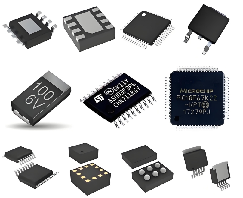
1. OUTPUT A: Output of Comparator A
2. INVERTING INPUT A: Inverting (-) Input of Comparator A
3. NON-INVERTING INPUT A: Non-inverting (+) Input of Comparator A
4. GND: Ground
5. NON-INVERTING INPUT B: Non-inverting (+) Input of Comparator B
6. INVERTING INPUT B: Inverting (-) Input of Comparator B
7. OUTPUT B: Output of Comparator B
8. VCC: Positive Supply Voltage
Application Circuits
The open-collector output and ground-sensing capability of the LM393DG make it incredibly flexible. Here are two common application circuits:
1. Basic Non-Inverting Comparator:
This is the simplest mode of operation. The reference voltage is applied to the inverting input (-), and the variable input signal is connected to the non-inverting input (+). When the input signal rises above the reference voltage, the output transistor turns off, and the pull-up resistor pulls the output voltage high (to Vpull-up). When the input signal is below the reference, the output transistor saturates, pulling the output voltage low (near GND). This circuit is perfect for over-voltage or under-voltage detection.
2. Dark-Activated Switch (Light Sensor):
This practical circuit uses a comparator to control a relay or LED based on light levels. A Light-Dependent Resistor (LDR) and a potentiometer form a voltage divider connected to the non-inverting input (+). Another voltage divider sets a fixed reference voltage at the inverting input (-). By adjusting the potentiometer, you set the trigger point. In darkness, the LDR's resistance is high, causing the voltage at the non-inverting input to exceed the reference voltage. This makes the output go high, turning on a transistor which then activates a relay or LED. When light falls on the LDR, its resistance drops, the voltage on the non-inverting input decreases, and the output goes low, turning the load off.
ICGOODFIND: The LM393DG stands as a testament to timeless design, offering a perfect blend of simplicity, robustness, and low-power operation. Its open-collector output provides unmatched flexibility for level-shifting and driving various loads, cementing its status as an indispensable tool for both hobbyists and professional engineers in analog circuit design.
Keywords: Open-Collector Output, Low Power Consumption, Voltage Comparator, Differential Comparator, Single-Supply Operation.

